D flip-flop
1
2
3
4
5
6
7
|
module top_module (
    input clk,
    input d,
    output reg q );
    always @(posedge clk)
        q <= d;
endmodule
|
D flip-flops
建立一个8bit的D触发器
1
2
3
4
5
6
7
8
|
module top_module (
    input clk,
    input [7:0] d,
    output reg [7:0] q
);
    always @(posedge clk)
        q <= d;
endmodule
|
DFF with reset
建立一个8bit的D触发器,带同步高电平复位
 1
 2
 3
 4
 5
 6
 7
 8
 9
10
11
12
|
module top_module (
    input clk,
    input reset,            // Synchronous reset
    input [7:0] d,
    output reg [7:0] q
);
    always @(posedge clk)
        if(reset)
            q <= 0;
    	else
            q <= d;
endmodule
|
DFF with reset value
建立一个下降沿触发的8bit的D触发器,带同步高电平复位,复位时,将触发器的值设置为0x34
 1
 2
 3
 4
 5
 6
 7
 8
 9
10
11
12
|
module top_module (
    input clk,
    input reset,
    input [7:0] d,
    output reg [7:0] q
);
    always @(negedge clk)
        if(reset)
            q <= 8'h34;
    	else
            q <= d;
endmodule
|
DFF with asynchronous reset
建立一个8bit的D触发器,带异步高电平复位
 1
 2
 3
 4
 5
 6
 7
 8
 9
10
11
12
|
module top_module (
    input clk,
    input areset,   // active high asynchronous reset
    input [7:0] d,
    output reg [7:0] q
);
    always @(posedge clk, posedge areset)
        if(areset)
            q <= 0;
    	else
            q <= d;
endmodule
|
DFF with byte enable
建立一个16bit的D触发器,带2bit的字节使能byteena[1:0],带同步低电平复位
 1
 2
 3
 4
 5
 6
 7
 8
 9
10
11
12
13
14
15
16
17
|
module top_module (
    input clk,
    input resetn,
    input [1:0] byteena,
    input [15:0] d,
    output reg [15:0] q
);
    always @(posedge clk)
        if(~resetn)
            q <= 0;
    	else begin
            if(byteena[1])
                q[15:8] <= d[15:8];
            if(byteena[0])
                q[7:0] <= d[7:0];
        end
endmodule
|
D latch
1
2
3
4
5
6
|
module top_module (
    input d,
    input ena,
    output q);
    assign q = ena ? d : q;
endmodule
|
DFF
建立一个带异步高电平复位的D触发器
 1
 2
 3
 4
 5
 6
 7
 8
 9
10
11
|
module top_module (
    input clk,
    input d,
    input ar,   // asynchronous reset
    output reg q);
    always @(posedge clk, posedge ar)
        if(ar)
            q <= 0;
    	else
            q <= d;
endmodule
|
DFF
建立一个带同步高电平复位的D触发器
 1
 2
 3
 4
 5
 6
 7
 8
 9
10
11
|
module top_module (
    input clk,
    input d,
    input r,   // synchronous reset
    output reg q);
    always @(posedge clk)
        if(r)
            q <= 0;
    	else
            q <= d;
endmodule
|
DFF + gate
实现如下电路

1
2
3
4
5
6
7
|
module top_module (
    input clk,
    input in,
    output reg out);
    always @(posedge clk)
        out <= in ^ out;
endmodule
|
Mux and DFF
如下电路中,实例化了3个D触发器+选择器模块,实现D触发器+选择器模块
1
2
3
4
5
6
7
8
9
|
module top_module (
    input clk,
    input L,
    input r_in,
    input q_in,
    output reg Q);
    always @(posedge clk)
        Q <= L ? r_in : q_in;
endmodule
|
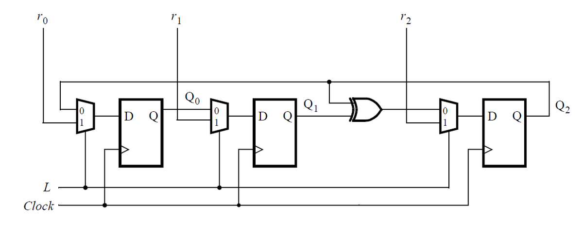
Mux and DFF
如下电路是n-bit移位寄存器
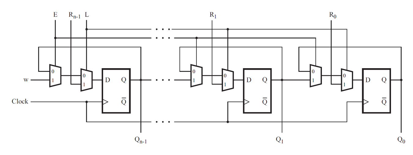
实现其中一级,包括D触发器和选择器
1
2
3
4
5
6
7
8
|
module top_module (
    input clk,
    input w, R, E, L,
    output reg Q
);
    always @(posedge clk)
        Q <= L ? R : (E ? w : Q);
endmodule
|
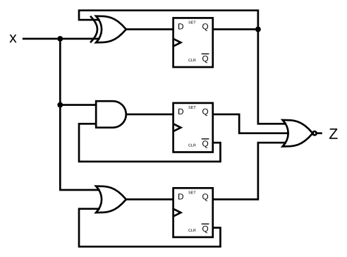
DFFs and gates
实现如下电路
 1
 2
 3
 4
 5
 6
 7
 8
 9
10
|
module top_module (
    input clk,
    input x,
    output z
);
    reg [2:0] st = 0;
    always @(posedge clk)
        st <= {x ^ st[2], x & ~st[1], x | ~st[0]};
    assign z = ~| st;
endmodule
|
Create circuit from truth table
| J |
K |
Q |
| 0 |
0 |
Qold |
| 0 |
1 |
0 |
| 1 |
0 |
1 |
| 1 |
1 |
~Qold |
使用DFF和逻辑门建立JK触发器,实现上述真值表
 1
 2
 3
 4
 5
 6
 7
 8
 9
10
11
12
13
14
|
module top_module (
    input clk,
    input j,
    input k,
    output reg Q);
    always @(posedge clk) begin
        if(~j & k)
            Q <= 0;
        else if(j & ~k)
            Q <= 1;
        else if(j & k)
            Q <= ~Q;
    end
endmodule
|
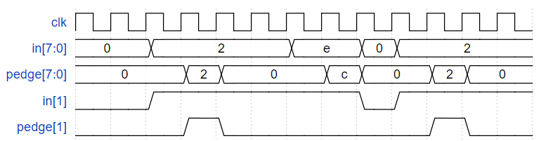
Detech an edge
检测8bit输入的上升沿,波形如下:
 1
 2
 3
 4
 5
 6
 7
 8
 9
10
11
12
13
|
module top_module (
    input clk,
    input [7:0] in,
    output [7:0] pedge
);
    reg [7:0] q1, q2;
    always @(posedge clk) begin
        q1 <= in;
        q2 <= q1;
    end

    assign pedge = q1 & ~q2;
endmodule
|
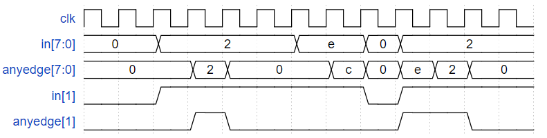
Detect both edges
检测输入的双边沿,波形如下
 1
 2
 3
 4
 5
 6
 7
 8
 9
10
11
12
|
module top_module (
    input clk,
    input [7:0] in,
    output [7:0] anyedge
);
    reg [7:0] q1, q2;
    always @(posedge clk) begin
        q1 <= in;
        q2 <= q1;
    end
    assign anyedge = q1 ^ q2;
endmodule
|
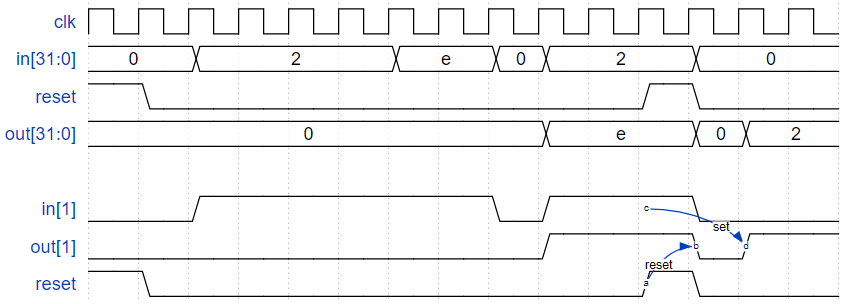
Edge capture register
捕捉32bit输入的下降沿,即当出现下降沿时,输出将变为1并保持,同步高电平复位,波形如下
 1
 2
 3
 4
 5
 6
 7
 8
 9
10
11
12
13
14
15
16
17
18
19
20
21
22
23
|
module top_module (
    input clk,
    input reset,
    input [31:0] in,
    output reg [31:0] out
);
    reg [31:0] q;
    always @(posedge clk)
        q <= in;

    integer i;
    always @(posedge clk) begin
        if(reset)
           out <= 0;
        else begin
            for(i = 0; i < 32; i = i + 1) begin
                if(q[i] & ~in[i])
                    out[i] <= 1'b1;
            end
        end
    end

endmodule
|
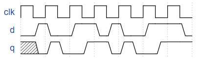
Dual-edge triggered flip-flop
实现一个双边沿触发的D触发器,但不要在一个always里面同时使用上升沿和下降沿,这是不可综合的
波形如下
 1
 2
 3
 4
 5
 6
 7
 8
 9
10
11
12
|
module top_module (
    input clk,
    input d,
    output q
);
    reg pos, neg;
    always @(posedge clk)
        pos <= d;
    always @(negedge clk)
        neg <= d;
    assign q = clk ? pos : neg;
endmodule
|